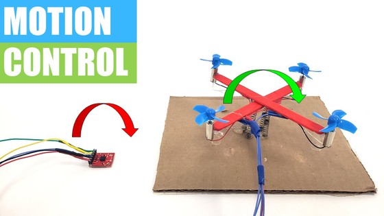
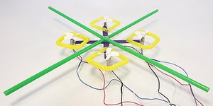
DIY Mini Drone: Motion Control
Summary
Introduction
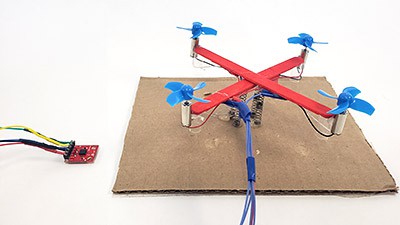
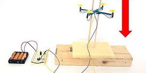
Most modern smartphones and video game controllers have a built-in accelerometer used for motion control. In this project you will program an Arduino® to use an accelerometer to control the steering of a miniature popsicle stick drone.
See this page for a complete list of our mini drone projects. You may wish to do the projects in order.
Materials
- DIY Mini Drone Kit
- Science Buddies Electronics Kit for Arduino
- You will also need to gather these items, not included in the kits:
- N-channel MOSFET (4)
- Push button (4 total, 2 included in Arduino kit)
- ADXL355 triple-axis accelerometer breakout board
- Male-female header pins
- Soldering iron
- Lead-free solder
- Optional: Heat shrink tubing and heat gun
- Identical retractable pens (4)
- Piece of corrugated cardboard
- Scissors
- Windows or Mac computer. Unfortunately, Arduino software does not currently work well with Chromebooks. Your computer will need:
- Access to the Arduino IDE, either installed local version or web-based editor. Watch this video for a comparison of the two options.
- USB port. The Science Buddies kit comes with a USB-A to B cable. The "B" end plugs into the Arduino and the "A" end plugs into your computer. You will need an adapter or different cable if your computer only has USB-C ports. Watch this video to learn about the different types of cables and adapters.
Disclaimer: Science Buddies participates in affiliate programs with Home Science Tools, Amazon.com, Carolina Biological, and Jameco Electronics. Proceeds from the affiliate programs help support Science Buddies, a 501(c)(3) public charity, and keep our resources free for everyone. Our top priority is student learning. If you have any comments (positive or negative) related to purchases you've made for science projects from recommendations on our site, please let us know. Write to us at scibuddy@sciencebuddies.org.
Prep Work
- Follow the instructions in the Program Drone Steering with an Arduino® project to build your drone and the Arduino circuit.
- The accelerometer breakout board does not come with header pins attached, so you will need to solder them on yourself. Refer to the Science Buddies soldering tutorial if you do not know how to solder.
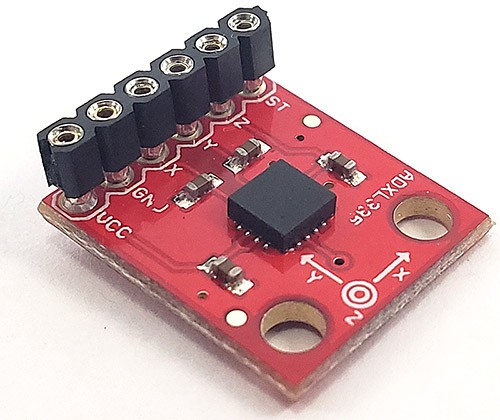 Image Credit: Ben Finio, Science Buddies / Science Buddies
- Solder short pieces of solid-core jumper wire to the ends of five 1 m pieces of stranded wire. Wrap the exposed solder connections in electrical tape or, if available, use heat shrink tubing.
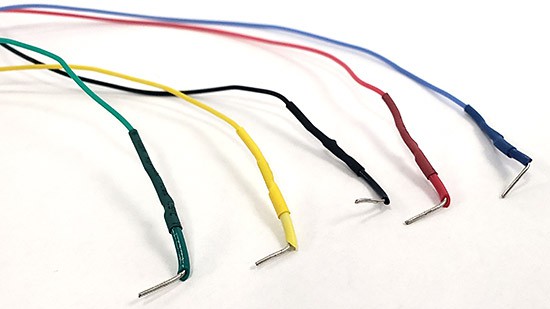 Image Credit: Ben Finio, Science Buddies / Science Buddies
- Plug one end of each wire into the header pins on the accelerometer. You will plug the other ends into your Arduino in the next section.
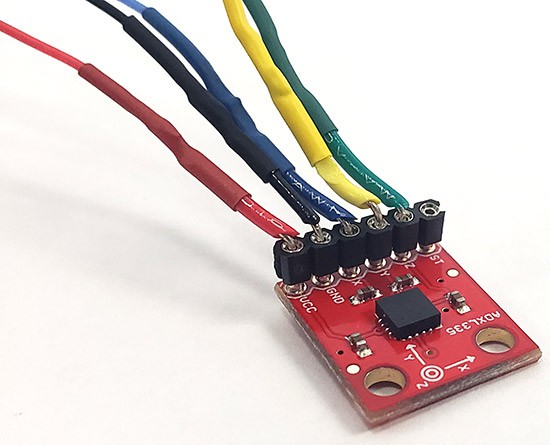 Image Credit: Ben Finio, Science Buddies / Science Buddies
Instructions
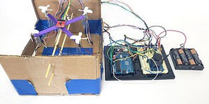
- Modify your circuit as shown in the diagram below (click for a bigger version of the breadboard layout or circuit diagram).
- Remove the four pushbuttons and associated jumper wires.
- Connect the accelerometer breakout board to the Arduino as follows:
- VCC to Arduino 3V3.
- GND to Arduino GND.
- X to Arduino A0.
- Y to Arduino A1.
- Z to Arduino A2.
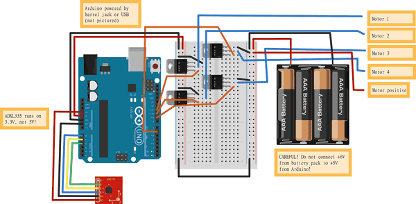 Image Credit: Ben Finio, Science Buddies / Science Buddies
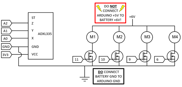 Image Credit: Ben Finio, Science Buddies / Science Buddies
- Disconnect one of the battery pack's wires for now to prevent the drone's motors from spinning. Due to manufacturing variation, the voltages that different accelerometers produce in response to the same acceleration will not be exactly equal. You need to calibrate your accelerometer before you continue.
- Download motion_control.ino and upload it to your Arduino.
- Select Tools → Serial Monitor to open the Arduino's serial monitor. The serial monitor will print out values for a bunch of the variables in your code. For now, you only need to look at the voltages. They are listed in order: Vx, Vy, and Vz.
- Place the accelerometer perfectly flat on a level surface and record the values for Vx and Vy. Make sure the accelerometer is not moving when you record the values. It is okay if the values fluctuate slightly. Do your best to record an average value.
- Tilt the accelerometer 90 degrees so it stands vertically on any edge. Record the value for Vz.
- In the code, change the values of x_bias, y_bias, and z_bias to match the voltages you recorded. The datasheet for the ADXL335 says that these voltages should be between 1.35 and 1.65 V for the x and y axes, and between 1.2 and 1.8 V for the z axis.
- Save and re-upload your code.
- Rotate the accelerometer so it stands vertically on an edge parallel to the y axis. The pitch angle printed to the serial monitor should be approximately 90 degrees. If it is not, adjust the gain variable in the code, then re-upload and try again. According to the datasheet, the gain should have a value between 270 and 330 mV/g. Keep changing the gain until you get a value close to 90 degrees when the accelerometer is standing on its edge. Remember to re-upload your code each time you change the variable.
- When you have finished this process, your accelerometer is calibrated.
- Place the accelerometer flat on a level surface, then reconnect the battery pack to the breadboard. Your drone's motors should start spinning.
 What happens when you run the code and tilt the accelerometer side to side or front to back?
 - Try changing the value of the variable a in small increments (for example, from 0.02 to 0.025 or 0.015). Re-upload your code.
How does the drone's response to tilting the accelerometer change when you change the variable?
Cleanup
What Happened?
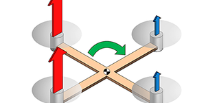
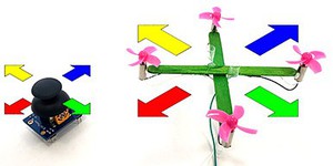
When you tilt the accelerometer, the Arduino calculates its angles of roll (side-to-side tilt) and pitch (front-to-back tilt). The code then adjusts the speeds of the motors to make the drone tilt in the same direction. This is the same concept used in the Program Drone Steering with an Arduino® and Drone Control with an Analog Joystick projects, but instead of using buttons or a joystick, your circuit uses the accelerometer as an input. Read the Digging Deeper section to learn more about how accelerometers work.
The variable a changes the drone's sensitivity to the accelerometer's tilt. Increasing the value of a will make the response more sensitive, meaning the drone will respond more quickly to smaller rotations of the accelerometer.
Digging Deeper
The accelerometer you used in this project is a three-axis accelerometer. This means it can detect acceleration in three perpendicular directions, labeled X, Y, and Z. If the accelerometer does not rotate at all (i.e. it stays level), then the accelerometer will detect motion in any of those three directions.
However, accelerometers have an interesting property: they also detect the direction of gravity. This means that if you hold an accelerometer still (do not move it side to side or up and down) and rotate it, it can tell which way is "up." For example, when the accelerometer board sits flat on a table, gravity points in the Z direction. If you tilt the accelerometer 90 degrees to one side, gravity will point in the X or Y direction depending on how you tilted it. If the accelerometer is partially tilted (e.g. 45 degrees), then there will be a component of gravity in more than one direction.
Your code uses this information to calculate the drone's roll and pitch angles. You can see the equations in the code, just below the comment "calculate roll and pitch in degrees." The equations are somewhat complicated and involve three-dimensional trigonometry, so do not worry if you do not understand them. You can read more about how accelerometers work and how they can detect gravity in this Accelerometer Technical Note. If you want to dive into the math behind how the roll and pitch angles are calculated, see the Additional Resources section.
Ask an Expert
For Further Exploration
- Try changing other variables in the code, like defaultSpeed or speedChange. What happens?


